I spend a bunch of time posting on FFCobra.com. Here is a list of
topics started just for fun, questions answered, or how-to's that I have
done over the past year and a half. The questions or comments
are in bold! I hope this helps!
This post on ffcobra started it all!
Hi All,
Is anyone running a small block Chevy in a FFR Mark II Cobra (Roadster)?
If so, how did the build go? I know that this can be a hot topic and I am
not trolling for a flame job. I am a die hard Chevy guy and have a 380hp 383
on an engine stand ready to go.
I am interested in things like:
How well did the engine fit?
What was needed to be done to the motor mounts?
How did the trans the cross member work out? (I'm planning a Tremec TKO
setup for a Chevrolet)
How did the driveshaft work out,
Was the pinion angle with an IRS acceptable?
I have seen a few people that have installed an LS1 and a Ford 460 fits so I
am pretty sure that a small block Chevrolet will go in there too.
My philosphy is this...
If you're restoring anything, make it original.
If you're trying to replicate something, make it original.
If you're building your dream, build it any way you want.
Resale value is not a factor.
Any and all helpful replies appreciated...
Seeya!
Randy
Can courtesy lights be put in the car and where do you get some cool
ones.
I got the idea from
Bob Mac and put them in my car. It's one of the coolest things at night!
Basically, I got two small light fixtures from Autozone (about $9 each) and
mounted them on the bottom of my 'Mike Everson under dash panel'. There is a
switch also mounted on the panel to operate them. To the driver's side of
the steering wheel.
I walk up to the car, reach under the dash, and hit the switch. The car
interior lights up like a production car!
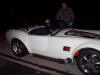
It had been raining and I decided to take the car out for a Christmas
day ride!
Hi all,
Well, it rained like mad on Thursday so most of the salt is gone for the
time being. Today, I decided to take the Cobra out for a short drive!
It was 14 degrees out and damn was it cold... But, it's an amazing rush to
get in that thing and drive it. I'm all warmed up now and the smile is still
here.
Here's a self portrait!

Post about the first drive!
Hey all,
We'll we did a bunch of head scratching today and pretty much decided that
we had a bad or upside down thermostat or air in the system. I came home,
checked the thermostat and it was in right. I gave it the boil test with the
digital thermometer and it opened right on que. We decided that I should put
everything back together and fill from the thermostat housing. (Less, I read
your post afterwards, GMTA) Anyway, when the engine got full and I tried to
put more water in the radiator via the upper hose, it came out the
thermostat housing. I put the thermostat back in and we fired it up. There
was a little air left but it never got above 185. After fussing with the
mixture and timing for awhile as well as letting it burp as much air out as
possible, we were ready.
The first tests were back and forth in the driveway to make sure the brakes
stopped it. They did. It took a bit of a push but it stops. I can't wait to
see what it does with some good Hawk pads. Anyway, everything seemed like a
go so I took it around the block with several simulated emergency stops. It
tracks dead straight and stops just as well. You can literally almost lock
up the wheels without having your hands on the wheel.
All I can say is that as much as you're ready for it, these things are twice
as fast as you think they're going to be. It's an absolute rocket.
This one of the best days of my adult life. I am pretty proud of how things
turned out. It's back in the garage with no squawks other than the
distributor needs to be re-curved so the timing is right on.
Julie took a movie well after the initial testing was done with my digital
still camera that turned out pretty well. (It's 50 megs so beware.) And here
is a link:
http://www.gpsconnection.com/project/1drive.mov
Right now, I don't have a way to make it smaller. If anyone has any ideas on
conversion to mpeg or something, let me know.
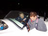
Pictures: The first one is me, the second, Julie and I, and the third is Al
driving, a great friend and the best engine guy I have ever met.
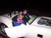
It's a good day, gentlemen. The beer afterwards tasted very good.
Thanks to everybody for all the help getting me this far.
How I fixed the issue with the door latch mounting on the Mark III
I just did this and
it turned out great. I have to say that it took me 4 hours to figure out and
an hour to do both sides.
The steps I did things:
1. Don't mount the latch assembly to the door first. It's the last thing
that gets done. It won't be anywhere near the little marks that look like
they should be used as a guide.
2. I tried to use the stock mounting tab that is welded to the frame but
then just decided I couldn't and cut it off.
3. Drilled out two of the four screw holes in the striker bracket larger so
that I could use a bolt instead. I think they were 1/4-20 stainless. When
the body comes off for paint, I am going to put the bolt through from the
other side and use a chrome acorn nut on the inside which is visible.
4. Drilled the 1/8" lower hole for the latch assembly (farthest from the
hinge) as low and as far away from the hinge as it will go and still hit the
mounting 'boss' that is molded into the door. I screwed the latch assy
loosely so that it would pivot.
5. Latch the striker bolt in the latch and put the striker bracket on the
striker bolt with no washers.
6. Rotate the whole assembly (it rotates around the one screw that we put
into the door) so that the striker bracket is parallel to the 3/4" steel
tube it's going to mount to. You're rotating the latch on it's one screw,
the striker bolt is latched in the latch, and the striker bracket is slid on
the striker bolt.
7. Slide the striker bracket in or out on the striker bolt making sure it's
near the center of the tube it's going to bolt to and that you also have
threads of the striker bolt visible so that you can put the 'finish nut' on
it.
8. Drill two holes through the striker bracket and through the 3/4 tube.
9. Add washers between the bracket and the 3/4 tube to adjust the bracket
(and the door) in or out. (note: I also had to grind a small amount of
material off the rounded bottom portion of the striker bracket. It contacted
the tube making the bracket too 'high' and made the door 'close too deep'
10. Add washers on the striker bolt on both sides of the bracket as needed
to adjust it so that it fits into the 'V' and the latch has good action.
11. I needed the FFR supplied spacer plates to space the latch assembly off
the door.
12. At this point, the latch assembly should sit flat on the door. Drill the
three remaining holes and screw it down.
I'll post pics tonight.
I really hope this helps those that come after me. It took a bunch of time
to figure out and very little time to actually do.
The first is the
driver's side and the last two are the passenger's side.
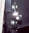
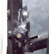
I had some
concerns about the three link being close to the rim. I was right
about the rim hitting on sharp left turns. I took a little material
off the bracket shown and all was well. The shock angle was correct.
Hi All,
I am just finishing up the 3link and have a couple questions for you guys
that have done it already.
1. In the first picture below, you'll see a part of the driver's side 3link
assembly. The issue is, the panhard bar is not in yet but I know the rear
end is too far to the driver's side. It also may be too low.. The area at
'A' is very tight and won't let the axle go toward the center of the car
enough to bolt up the other side. Where do these parts sit in relationship
to each other when the axle is full down against the limit straps? It seems
that the point 'B' should be well above where the end of arrow 'A' is.
2. When bolted up, my shocks aren't vertical as shown in by the red angle of
the 2nd picture. Is this correct? I have looked at tons of 3link build pics
and can't see that I'm doing anything wrong so it may be OK. Just to be
clear, I have two even spacers on the top and the one big spacer on the
bottom front and a 1/8 small washer on the bottom back.


Here was the
introduction to the webcam!
Hi all,
I had a webcam lying around that I wasn't using so I decided to mount it on
the wall facing the cobra project. It's a 1.3 megapixel and shoots a picture
every 30 seconds or so. It runs 24/7 so if you go there and it's dark, that
means the garage is shut and the lights are off.
I'm out there almost all the time I'm home.
It's just the picture right now but when I get a second, I'll put a page up
with a couple pictures of Julie and I on it as well as a quick cobra project
bio. (too busy for a build site but this is pretty cool)
Let me know what you think!
How do you change
from four lug to five on an 8.8 rear end?
It's easy. Swap in
Ranger or Aerostar axles and buy a couple of Richard Oben's brackets.
You need two driver's side axles from a pre 91 Ranger or any two passenger's
side ones from (I'm told any year) Aerostar.
The junk yard got me 50 bucks for the set.
Richards brackets are a bolt in but remember to have them in had when you do
the axle swap!
Here are my notes
from mounting the driver's side seat. It slides.
Using the tristates
seat rails which are not fancy but very functional, I was able to mount one
right side up and one upside down to have the desired effect. They go up an
incline of about 7 degrees and will allow both me (5'10") and Julie (4'10")
to drive it. The handle is in the middle of the seat, moves (right) toward
the tunnel to disengage and it is on the seat side so as you move the seat
forward or backwards, the handle is always in the same place with respect to
your butt.
I'm sure it's been discussed but I wanted to note for those doing this after
me that the seat rails are actually mounted slanted so the seat, when moved
forward, moves along the same plane as the transmission tunnel. The seat
faces dead nuts forward but actually moves toward the left as it goes
forward.
All in all, it worked out very clean.
Thoughts on the
Forte's tubular lower control arms:
I have '95 SN95
spindles and Forte's lowers and they work fine. If you have Bilsteins, make
sure you read about the spacer issue we have.
With the LCA's though, there's a small spacer that goes on the ball joint
bolt so that when you tighten it up, the hole in the ball joint bolt lines
up with the slots in the castle nut so the cotter pin slides in.
How long is an
FFR Cobra!
Just went out and
measured for you.
I get 12' 10" from 'nose to tail'.
I don't have quickjacks on so I measured from the tip of the license plate
light to the tip of the nose (which seemed to be the furthest forward point)
Early on, I had a
brake squeek. It was coming from both rear calipers. It turned
out that the pads were getting stuck on the caliper because of my paint that
I put on there. After cleaning and lubing them, all was well!
I just need a quick
sanity check on a squeak the Chevycobra has.
When I first started driving, I had a distinct hot brake smell from the
rear. It smelled like a dragging E brake had the rear brakes hot. It went
away in a couple miles and now, the tires spin fine by hand. (I'm confident
that nothing drags at this point)
Now, each time I go out and after a couple stops, I have a persistent
squeak. Initially, it was coming from both sides but more prominent on the
passenger's side.
Saturday, I swapped the rotor from passenger's to driver's side. Also, I
Scotch-Brighted the rotor just in case I glazed it.
The noise seemed to follow the rotor to the driver's side although it
doesn't seem nearly as bad. I know now that both sides are squeaking nearly
the same level.
It's definitely one squeak per tire rev and it goes away when I depress the
brakes.
I assume that I might have warped the rotors but before I have them turned,
I my plan is to replace the rear pads with semi-metallic pads.
Also, I know there is no anti-squeak glue on the pads now so I will put some
of that stuff on there.
Does this sound like a sound plan? Is there any other suggestions that you
guys have?
You don't need
the axle limit straps when using my configuration. FFR said it was
true and what do you know, I could take them off!
I just wanted to
mention that I took axle limit straps off this weekend because the popular
information right now is that if you have Bilsteins, you don't need them.
However,
When I removed them at first, my rear end was allowed to come down so far
that the driver's side bottomed out on the Panhard bar triangular bracket
before the springs stopped it.
I moved the upper shock mount to the upper set of holes and it was perfect!
The setup is:
Mark III
'88 Tbird Turbocoupe (fox width) with disc brakes
Factory 3 link setup
Bilsteins
A major milestone
for me and my post talking about it!
Hey guys!
Every now and then you get a day that is one to remember. For me, today was
one of those days.
About noon, we loaded the Rollerblades up in the Cobra's trunk and went down
to the Erie canal. They have an awesome bike path that goes for miles and
miles. There, we skated about 10 miles round trip and returned to people
standing around the car wondering what it was. After a few questions
answered, we were off.
Next, we stopped at Jul's parents house to water plants, and then over to
our friend's house who haven't seen the car on the road yet. Well, both
wanted to go for rides! Jamie (him) went first and said he was really
impressed by the solid feel and (at least from the passenger's seat), said
it felt really balanced. Jamie has a Porsche Boxter so he's into sports type
cars. Next, Cherie (her) got in. I started it up and she got this grin on
her face. Around the corner and stopped at the stop sign, she says: "Light
it up! ...You won't scare me!" I'm still breaking my engine in but I will
tell you that we still left really hard! There was definitely a squeal from
the right seat!
After the short visit, we went to store to get groceries! (Pic attached)
At home, I threw some steaks on the grill, opened a bottle of Yuengling and
then talked with Robert Feddersen where I learned that he got his car
running again and it runs great!
Then, with some Phil Collins on the stereo, Jul and I had a great dinner.
Here is a picture of the car with the rollerblades and groceries in it!
![[Big Grin]](http://www.ffcobra.com/ubb/biggrin.gif)

I don't need anything else today...
It was truly a wonderful day to be alive!
What size tires
am I using and what would I like next time?
I'm using FFR
Bullits and have 245-45-17 Sumitomo HTRZ's. They fit fine but I might get
255-45-17's next time. The only issue with the 245's is that they're
'exactly' the width of the 9" rim. Thus, the tire won't protect the rim at
all if I accidentally curb the car.
Information about
those that use Forte's front lower control arms and how the spacers interact
with the ride height.
Hi,
No disprespect to Mike but his spacers made some (possibly all) our Mark
III's too high in the front. It took us awhile to realize that the spacers
made the front end higher than we wanted even with the shock adjustment all
the way 'lowered'.
I'm still VERY happy with his lower control arms but I had to remove his
spacers. I'm sure he has probably changed the size of the spacers now so
give him a call.
I ended up finding the right sized grade 8 washers that fit perfectly and
added them until the cone didn't touch the LCA at full droop.
Just did this tonight so it's fresh in my mind.
I'm happy to answer questions about my setup if you have em!
So, how much lube
does an empty 8.8 live axle need?
It will take a
little over two quarts plus the Friction Modifier. I had to make another run
to the store to get a third quart. Of which, I used about 1/3.
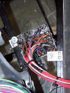
Why do I have a
battery cutoff switch?
I installed one for
two reasons. I like the idea about being about to turn the battery off
completely. I was obsessive about my short postitive battery run from the
battery to the switch so I know that if the key is with me,
1. There is, for all reasonable purposes, no chance of an electrical fire.
2. It's another layer of theft protection.
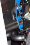
Automatics need
transmission coolers. Here is how I mounted mine and the post I did
for it. You can't even see it unless I point the hoses out to you!
Hi All,
Just thought I'd post what I finally came up with regards to the trans
cooler and fan controller.
Trans cooler - Hayden 12 x 7 (or something like that) mounted in between the
fan and radiator. I made two AL strips and mounted the cooler to them using
the zip ties it comes with. That way, nothing protrudes out the front of the
radiator.

Fan controller - Autozone adjustable and it's wired so it can control the
fan even with the key off. I still have a manual override on the dash just
in case I want to turn it on myself.
If you look closely, you can see the capillary tube probe mounted on one of
the strips. When the shroud is mounted, the probe is about 1/8" from the
fins of the radiator.
The controller is mounted on the outside of the fan shroud over near where
my relays are. (In the upper left of this picture:

The controller with it's adjusting screw:

I'm really happy with the way it came out. We'll see how it works in
practice!
So, what is your
FFR number and where is it located?
This is an
interesting topic and one that we've discussed before but most agree (me
included) that your Mark III FFR number is the number that is 'engraved' on
your car and matches your FFR Certiticate of Origin.
It will be something like mine: FFR1004114RD
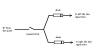
How do you wire
the hazard lights?
Here's how it's
supposed to go. The diodes keep one side from back-feeding though the hazard
connection into the other side when you want only right or left turn signal.
I hope this helps!
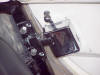
What gauges am I
using?
Here are two
pictures of my 5" tach and speedo Autometers for comparison. It's certainly
a few hundred dollar option over using the donor...


The rear Exhaust
hangar isn't exactly clear in the manual so I drew this up after I figured
out how it goes.
Every now and
then, somebody will post the question about if it's worth it to pick your
kit up at the factory. It's totally worth it! Here is a post
with a few pictures about that.
I agree, make the
trip!
You can do it easy with a U-haul car hauler also. Here are a couple pictures
taken on the day I met the 'ChevyCobra for the first time!
You'll need at least four big ratcheting tie downs. I built the cradle that
you see in the pictures. If you need anything while you're there, there is a
Home Depot right down the street from the factory!
Jul and I are going to bring the car back there this summer just for fun!


The famous
Minicooper Light install howto that I wrote. Thanks again to Tony A
for being the first. I was the 2nd!
Hi All,
I just installed my Mini Cooper backup (reverse) light yesterday and if I
didn't have to look around for the tiny terminal connectors, it would have
been about an hour's job. It's really inexpensive, easy, and looks great!
Anyway, I took a bunch of pictures and decided that I would post a 'howto'
here just in case those that follow us can use it.
Thanks to Tony A for the initial information!
Stuff you'll need (or want)
- Mini Backup light
- Tiny push on crimp terminals. I think they're used for small car speakers.
(I got mine at an auto parts store. Radio Shack and Home Depot didn't carry
them that small)
- Dremel with the sanding drum on it.
- Sabre saw
- Drill motor and a large sized bit or a step drill.
- Sharpie (or equivalent marker)
- Silicone
Step 1.
Get a Mini Cooper backup light assembly from a Mini dealership.
The part number is: 63-22-1-477-678
They cost about 10 dollars depending on where you go and are a really nice
part. The pricing has to be a mistake as there is no car part ever that was
this nice and cost so little.
Step 2.
Prep the light. As you can see in this picture, there are these little
'ribs' on the light that would prevent you from inserting it in the hole
you're going to cut in your body.

30 seconds with the Dremel sanding drum and they're gone like in this
picture:

You'll also notice that I cut the plug. My original intention was to solder
wires onto it but the lugs are chrome so push on terminals had to be used
instead. I put a dab of silicone on top of them to keep corrosion down.

Step 3.
Locate your hole. Make sure you don't hit the trunk floor and that you find
center. I decided center was the middle between the two lower quickjack
mounting bolts. It may not be exactly center when paint is applied and if
not, I'll have my painter move the hole. ...but you get the idea.
Step 4.
Set the light, face toward the car and use a Sharpie to trace around the
lens, essentially making an oval the shape of the light.
After you've traced the outline, you need to 'freehand' another oval inside
the first. Keep in mind that your actual hole has to be smaller than the
outside oval on the light. This will keep the light from pushing right
through. Instead, it will stop at the 'flange'.
Here is a picture of the two ovals on the car with a sharpie:

Step 5.
Drill a few holes inside that are big enough to get your sabre saw blade
into.
Step 6.
Cut the oval with your sabre saw but leave yourself some room. Don't cut
right up to the line, you'll sneak up on the actual size with the dremel.
Step 7.
Use your dremel again with the sanding drum to open up the hole. Keep
putting the light in the hole and open it up so that it's a snug fit but not
too tight. You'll use silicone on the back side to keep it in.
Here's a picture of the hole all finished:

Step 8.
Wire it! I picked up a frame ground right near the light and soldered my
reverse light with a piece of shrink wrap.
Step 9.
Push the light all the way to the 'flange' and put a bead of silicone on the
backside to keep it in.
Step 10.
Have a beverage of your choice! Like I said, it was really easy and one of
the funnest projects of the build so far!
Here's a picture of how it looks finished:

If you have questions or comments, feel free to ask! There are a bunch more
pictures of the light assembly on my website at the bottom of the photos
section.
Have fun!
Where did I have
my Chrome parts done?
This is just a quick
note to say that after calling a bunch of places found here and otherwise,
my chrome parts are headed out to Mike at Kerr West.
Mike is a really nice guy who, apparently, does great work (so said a few of
you), and his pricing is great.
Mike,
Kerr West Plating
4737 N. 43rd Ave.
Phoenix, AZ 85031
(623)937-8676
Where did I mount the fuse box?
Mine worked great
here (next to the pedal box on the driver's side):
There was a
question about if the stock battery cable that FFR sends will work.
I'm running 10.5:1
with the FFR supplied positive cable and a high torque planetary geared
starter with no trouble at all.
Notes on mounting
and balancing of tires this big
For 17x10.5" rims,
they need special equipment. Also, there are tire mount machines that are 'touchless'
and can't mar the rim.
Not just any tirerack.com affiliate can do it. You'll have to call around.
I had my tires road-force balanced on a Hunter 9700 (The best they make)
To mount and balance with hidden stick on weight cost me $155 total (out the
door)
Occasionally,
someone will post a question about if they should buy a built car or build
one themselves. Here was a reply.
Hi and welcome!
My advice would be to drop by a couple builds going on in socal and offer to
help for a few Saturdays. Even if it's passin tools, I'm sure guys would
welcome the chance to talk with you about the build and show you some
things.
If, after seeing some cars in construction and helping out a little, you
decide it's still something you don't 'want' to do, then buy a completed car
and have great fun. Maybe you'll build one at some point.
If you think you'd be interested at all in building one and you think the
hangup would be skill, build it! There are guys that didn't know how to
change their own oil before their kit arrived. Building one of these things
is easy with the forum and real live 'cobra-buddies' around to keep you in
the center of the road.
I'm almost done and can say for sure that, so far, it's been the most
rewarding thing I've ever done.
When people ask where did I get it, I look forward to saying 'I built it!'.
If you would like to talk on the phone about it, I'd be more than happy to
answer any questions about my build. Just PM me your phone number.
Hope this helps! 'HTH'!
What front end
parts am I using? (steering and such)
Atsco 6812 18:1
manual rack
breeze polyurethane offset bushings lowing the rack (but I'm told you don't
need them with Mark III.)
FR tie rod ends
1995 Sn95 front spindles.
The lower shaft comes standard with the kit from FFR but you have to tell
them that you're going to use a manual rack so they can give you the right
one.
The best
suggestion when building (and then registering)
Make sure that all
your paperwork is in order. The registration turmoil varys from state to
state but the common thread is:
They want to make sure the major components are not stolen.
In an effort to do that, the burden of proof seems to be on us when
registering.
Suggestions:
If your state allows you to meet emissions by engine date code, buy a
'seasoned block' with a casting date of 1973 or earlier.
If you buy an engine from a retail store, get a receipt and have them write
the serial number on it. Actually look at the engine and make sure that the
serial number is the original stamping from the factory without
question.
If you buy a donor, make sure it's a 'numbers matching' car and that it has
never been stolen in it's life. You can verify this easily via Carfax or
your local State Police. If it has been stolen at some point and recovered,
it could be completely not worth the trouble.
Summary:
A ton of people in the past have registered their cars using 'something
other than their legit state DMV way'. Tust me, those methods are not
available like they used to be. (I'm not getting into the legal or moral
discussion here, that's another topic.)
Let's just say that I am lining up my ducks in prep for the NYS registration
process and have hit some roadblocks.
If I had planned correctly in the beginning, things would be a little
smoother right now. I knew building the car would be a journey and this too
will pass (so to speak) but I just wanted to share some learned items.
Which Turbocoupe
will give you five lug axles and all the right brake goodies?
1987 or 1988
Thunderbird Turbocoupe. Or, you can buy loaded calipers and new discs from
Autozone and Richard's brackets. That way, everything's new. I think the
calipers were something like $120 for the set and the discs were about $30
each. They will have to be redrilled if you're running 5 lug.
Here's a post
that I did showing how I mounted the stock supplied battery box underneath
the trunk floor. (only the top sticks up)
It's in the back
still so it wouldn't be an option if your main goal was to make the cable
lines shorter.
In case you're interested though, I used the stock FFR battery box and
hangars to mount it flush with the trunk. The only think that sticks up is
the cover. Here's a picture with more on my website:
HTH!


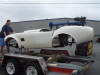
How do you unload
the kit from the trailer. The body is bolted to the frame.
Lift it right by the
body with one guy on each wheelwell on the curved part and if you have two
more, one guy on the top of the front air intake and one in the back.
Set it on four jackstands in the garage.
How did I do my
brakelines?
I'd run Tristates
lines again in a second. Really easy and fit 'fairly' well. There was a
little forming involved but it was relatively a non-event.
Well worth my money.
Post regarding
the fabrication of the headers.
Hey everybody,
If you were interested in the webcam, today would have been a good day to
check. A friend of mine and I built the headers for the ChevyCobra from
start to finish and it took all day. They are 4 into 4's for the late model
side pipes and I'm really happy with them.
As far as I can tell, there's only putting antifreeze in it, set the timing,
and light the fire. (There's probably a few more tiny things but right now,
I can't think of any.)
Here are a couple pictures.
If you think you
have a battery drain, how you would go about proving it.
If you have an 'amp' meter that you're familiar with and a battery cutoff
switch, hook the battery up with the switch off and measure current (on the
10amp or more scale) across the terminals of the cuttoff switch. You should
have no (or something way less than a 500ma load. The load assumes you have
a computer or clock.) If you have neither, there should be no load at all.
If you don't have an ampmeter, I would:
1. Unplug the computer (if there is one)
2. Test for continuity between the positive cable and the negative one.
There should be very little (if any) resistance there. Assuming there is
none, proceed. If there is, you may have something shorted or loaded (on)
that you don't know about. Check everything.
3. Put your battery charger on 2amp or borrow a 2amp power supply and hook
the car to it with clip leads. Watch for any spark when you do(even very
small). If you see a spark, go back to 2. and check things. If you don't see
a spark, go to step 4.
4. Hook up the battery and see what happens. Turn on things one at a time
and test.
ALWAYS turn the battery disconnect off unless you're standing right near the
car.
(Initially and until you really trust things.)
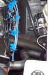
Here is a post
regarding the upper hose. Keeping in mind that it's a Chevy,
everything that goes from the engine to the car is custom.
Each part of
building this car is a challenge I win. Sometimes it takes more effort than
others but tonight, I had a big win. My upper radiator hose looks completely
factory sanitary.
I'm using a Summit Aluminum radiator (Chevy pattern) and the Summit one
piece filler with the cast flange (not the Moroso with the bonded sheet
metal flange). I'm using the FFR lower hose piece that we get with the kit
on the top near the radiator and another bought hose slightly trimmed down
on the engine side.
It's all in the engine compartment and doesn't touch anything. The pictures
don't really show it but the cap is the highest point in the system and the
outlet for the barf-bottle exits right toward the left-F panel where it will
be mounted.
Score one for the good guy tonight, I'm proud of it.
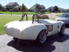
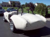
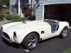
Pictures:


First body test
fit!
It finally looks
like a car.
After spending all day yesterday with the wiring, I made up some excuses to
put the body on today for the first time. It slipped right on.
I'm really excited...
Here are a few pictures.
We should be making some noise in a few weeks!
Sometimes, you'll
find there's a little slop in the steering shaft and it's coming from where
the upper DoubleD tube meets the lower steering shaft. Here are some
notes on that.
The double-D shaft has a hole in it. Per the manual, I drilled the
corresponding hole in the double-D tube and the shaft fits in the tube with
the hole lined up. No problem.
I will run a hardened bolt and nyloc in the hole to hold them both together.
The trouble is, there is a little slop in the wheel and it's at that
junction.
It's not much but with the wood wheel, it's about 5 degrees so I'd like to
get rid of it.
Tightening the bolt until it pinches the slop away is what I did and it
worked great. After I did that, I took the bolt out and put a new
'unstressed' grade 8 bolt in there.
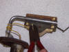
Where are the
engine mounts located on my car?
I have been asked a
couple times about the measurements of my engine mounts. I took a couple
pictures to give you guys an idea. Keep in mind that these are close but not
perfect as your setup may differ from my a little bit.
The first shows the distance between the mounts (both front and back) and
also the height of them.

The second picture shows how far back behind the 4 inch round cross member
they are.

I hope this helps! If there is anything I can help clarify for you guys that
are building or considering a Chevy, let me know! I'm here for you!
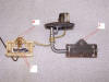
What type of
engine mounts did I use?
Here is a picture of
the engine mounts I used and a link to where I purchased them.

I bought them from
www.speedwaymotors.com and they are sort of hard to find on their site.
The part number is: 91018031 so if you 'search' the site for that, you'll
find them. Here is the description:
91018031
Universal Weld-On Motor Mounts
Fit most frames. 1⁄8" steel, 6" long, uses 1⁄2" bolt for engine mount.

Basically, I radiused the bottom 'square part' so that it would fit the 4"
round tubing and welded them in. I'm also using normal polyurethane engine
mounts for the SBC from Summit.
Here is a short
list of things you will have to modify a solution to when installing an SBC
into an FFR:
You'll have to fab
up something for anywhere the engine touches the rest of the car. That means
stuff like:
- engine mounts (grinding and welding involved)
- trans cross-member (mild welding most likely)
- coolant hoses (very easy)
- different radiator (very easy)
- drive shaft (easy because you'll have a custom one made anyway). Just tell
the DS maker that you need one from whatever trans you have to a Ford 8.8
- headers (hardest part) Less Steger had luck with slightly modifying a set
of Shell Valley headers. A friend and I fabbed up my custom 4 into 4's in
one whole Saturday. When we were finished, they were ready to run.
I ordered my Mark III and had FFR not weld on any engine mounts. Then,
modified a set of Speedway Motors engine mounts to fit the 4" round tube.
How we built the
headers!
I thought about
going the flexible tubing pattern route but decided that it wasn't going to
be exact enough. Building headers right on the car wasn't bad at all. I did
it right with the body on.
Basically, here's what I did:
Bought:
- Header parts from the guys at Shell Valley including flanges (which I
ended up not using), 16 1 3/4" mandrel U bends, and 2" adapters to get from
the 1 3/4" pipe to the FFR 4 port flanges. (you can see these adapaters in
the pictures below)
- The header flanges I ended up using came from Speedway Motors.
- Set of two FFR 4 port flanges from FFR.
- a 16' (needed only 8') piece of straight tubing from a local steel tubing
supply place. Make sure you are dealing with the right sized tubing ID or OD
because it's going to make a difference.
The rest is straight forward in description but a little harder in practice
(not hard though) Just a lot of hacksawing!
I also borrowed a junk head to put on my work bench to keep the flange
straight while we were welding. any time you weld on the header flange side
of things, bolt it down to the head to keep it from warping.
1. shim up and mount the side pipes EXACTLY where you want them.
2. Bolt the flanges to the heads.
3. Bolt the 4 port flanges to the side pipes.
4. Cut two pieces of straight tubing to make the straight center two tubes
and tack them to the header flange and the 4 port flange.
5. carefully, remove the 'header' from the car and finish welding those two
pipes to 'sturdy' things up. Then, make the remaining pipes a 180 degree U
bend cut in two to make two 90's. (roughly)
6. Weld up all the seams where exhaust would leak out. (how's that for being
general!)
7. You will have to cut a little diamond shaped piece to go in the center of
the 4 port side. (You'll see)
Here are some pictures:


The 'Dave Smith
seal of approval'!
I was looking
through some pictures recently and found one of Dave and I while I was
vacation in Arizona and FFR was there for a spec race at PIR. I drove down
for the In-N-Out Burger get together and ended up spending about four hours
talking with Dave and a great bunch of guys.
Early in the evening's conversation, the topic of my Chevrolet came up and
Dave's reply was:
'Man, that's cool! These are modular cars and we want everybody to put in
any engine and drivetrain they want.'

Anyway, it was a great evening and if you ever get some time to spend with
Dave, definitely do it. He's a really good guy!
Whitby
convertible top installation - things I learned.
Hi all,
Just a couple things I wanted to note for those coming after.
-- Beg, borrow, or steal (or rent right from Whitbys) a 'lift the dot
punch'. The one I got was a squeeze kind which sort of looked like a big
staple gun. There is another type that looks like a big punch and is meant
to be used with a 'backing plate' and a hammer. I'm sure that it saved me at
least two hours and much frustration. You position the punch over your mark
and squeeze. (instant, perfect hole.)
-- You get black 'lift the dots' with the kit which are perfect for a black
top. My top was tan so I bought some polished stainless steel ones from my
boat-canvas friend. Tan top + bright snaps = nice look. (my opinion!)
-- You actually can pull the top too tight when gluing the front bows on.
(one of my front bows is rotated slightly but won't be noticed by anyone but
me)
-- The manual says 53 degrees but I didn't have batteries in my
inclinometer. So instead, we just loosened the windshield and moved it so it
perfectly matched one of the side curtains that we held up next to it.
(while indexing the bottom edge of the side curtain along the door) In
summary... To do this, you need no measuring tools at all.
-- I put the side (fore and aft) stringers in while stretching the front
because I figured that if I stretched one side more than the other, it might
have diagonal wrinkles when I put the stringers in finally. This worked
great and I would do it again next time.
-- When installing the little locking latches to the windshield bows, rivit
from the inside out.
-- Glue (with something other than contact cement) a small piece of fabric
to cover the rivit heads on the front bows themselves. That way, they won't
scratch the windshield frame when you install the front bows and pull it
down over.
-- Tap the holes into the windshield frame 6/32 and don't go too deep on the
one that will eventually hit the 'inner frame'. This will allow the screws
to go in perfectly.
-- You will have to trim the 'banding' where it goes around and into the
windshield bows on the sides. There's just not enough room inside for a
band, fabric, the windshield frame, and another band inside the bow
'channel'.
-- I had to install one extra 'lift a dot' in the 'valley' that is between
the rear body top (in front of the trunk) and the rear fenders. The top
wouldn't sit down in there with the stock spacing. Next time, I might think
a little 'outside the box' with the snap spacing back there and try to
evenly space the snaps while making sure one of them landed right in the
valley.
-- The manual was as good as everybody says it is.. Trust the dimensions
given. They were all perfectly right on.
The top looks great and I am completely happy with it! If it never gets any
tighter, that's fine by me because there are virtually no wrinkles at all in
it now. I'll add more to this when I remember something that might help.
Here is a post I
did that makes an analogy between electricity and water. I don't claim
to be the first to write something like this, I just claim that I didn't
read it first. I hope it helps!
Hey all,
I was thinking about analogies and trying to describe a few electrical
concepts. Here is an analogy between water and electricity. I wrote this up
and even though it's probably not an original idea or perfect, I hope it
helps the guys that are new to electricity understand a few things.
Here we go:
Electricity is very much like water. Forget volts for a little while and
just think about water flow, and electricity 'current' or AMPS.
The Supply:
Water: You have a large supply of water at your house and you have things
that consume water in the yard (like big sprinklers or a very small water
fountain).
Car: You have a supply of current at the battery and you have things that
'consume' current around the car. Examples are big headlights and a little
interior light, etc.
Current requirements of things:
Water: Things in the yard need water at different rates (they have different
requirements to work right) Your big sprinkler needs a ton of water to
squirt water over your whole grass while the tiny fountain just needs a
trickle. In order to supply enough water for your sprinkler, you need a
large sized hose. Your little water fountain only needs a small hose (like
would be on an aquarium) to work.
Car: Headlights need a lot of current, a small interior light needs a
little. In order to supply enough current to your headlights, you need a
large sized wire. For your little interior light, you only need a small
wire. (Wires are measured in 'gauges' and it's the reverse of what you would
expect.... smaller ga. number = larger wire. An 8 ga. wire would be larger
in diameter than a 20 ga. one)
Wire size continued (not a perfect analogy but works):
Water: If you use a hose that is too small for the requirement, it will
burst and leak. When water leaks, it sprays water everywhere.
Car: If you use a wire that is too small, it 'leaks' or heats up.
Incindentally, if a wire heats up enough, it will melt it's insulation and
catch fire.
It doesn't make economic sense to run large wires (like battery cables) to
everything you want to power in the car but instead, you want to run a
properly sized wire for the job. There are actually tables to tell you what
gauge wire to use for a given length run at for a certain 'current'
requirement.
Connection quality:
Water: If you have a poor hose connection, you get leaks.
Car: If you have a poor wire connection at a terminal, you get leaks (heat
and possible hot enough to have a fire)
Switches:
Water: If you try and control a large water draw (like your sprinkler) with
a tiny little water valve, the valve can't take the pressure and will leak
and spray water everywhere.
Car: If you try and control something large (like your headlights) with a
tiny little switch, it will heat up and worst case, catch fire!
Switches have different maximum rating on them. (meaning the current draw
they can handle)
Relays:
Sometimes, you need to control something large but trigger it on or off with
something small.
Water: If you want to turn your sprinklers on and off but use a small
aquarium hose to do the switch, think of it like a little kid standing out
close to your sprinkler with the big on/off valve in his hand. In addition
to the big hose connected to his valve, we also have a small aquarium hose
running out there too (and it's stuck in his belt and aimed at his face!).
you control the aquarium hose water from a little valve back at the house.
When you do this, your kid gets hit in the face by a little stream of water.
When this happens, he squeezes the big valve and turns your big sprinklers
on. It's best when the kid is very close to the sprinkler.
Car: Relays work the same way. They can switch a large current (that lights
need) with a little small wire being the 'trigger'. The advantage of this is
that you can use a large capacity relay to run headlights and trigger from a
delicate little fancy switch on the dash.
Relays are like switches and have a maximum rating that they can handle as
well.
Diodes:
Sometimes, we want current to flow one way but not the other.
Water: imagine you had a hose in your above-ground pool connected to the
spigot. When you turn the water on, it flows into the pool. If you turn the
water off and disconnect the hose from the house, water will siphon back out
of the pool onto the ground. It wouldn't do this if you had a one-way valve
in there that only allowed water to flow 'into' the pool but not back again
when the hose is disconnected from the house.
Car: Sometimes, we need to make sure that current flows one way and not the
other. Examples are in the hazard circuit or activating a single turn signal
dash indicator light from both left and right signals.
I'm sure there are many more but I can't think of any right now. I hope this
helps some a little or stimulates some discussion aimed at helping the
electrical beginner guys.
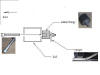
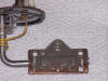
A lot of the
Mustang sending units are not working when they get to us. Here is a
tutorial that I wrote up that describes how to fix them. You really
can fix most of them.
I just went out and
opened another one that I haven't cleaned yet but as I thought, it looks
just like my other two did and it will work great.
I took some pictures!
(sorry for the lack of detail but wanted to get this in quick and I gotta
bolt for a Cobra ride to Syracuse!)
Here's the process:
Here's the sender:
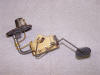
Here is the other side:
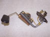
They melt this little post down to keep it from falling apart if the clips
let go. You must remove the melted plastic so it will go back through the
hole in the metal case piece. Diagonal cutters work well.
Then, you will see two L shaped parts of the plastic half on one side and a
plastic 'keeper' type spring loaded tab on the other. Once you activate the
spring loaded type side release, it will all come apart.
Here's a picture of the captures and you can see the L shaped one on the
left and the 'spring loaded type one on the right':
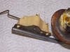
Here it is opened up like a clambshell with the plastic piece just opened up
and laid right over so you can see the relationship of the internal parts.
I used the sharp end of a Swiss Army Knife and a piece of sand paper to
clean the oxidation off the parts A and B (but not the coil) Don't really
wipe the coil with much other than a pencil eraser, it's fragile.
Here's a close up version of both halves:
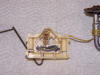
Put it back together in the reverse order!
A few guys recently have asked for the
Whitby top instructions. Jeff's top instructions are top notch but
they were in word. I converted them to a .pdf and as a result, the
file size is only 1.4mb.
Click
here to download them!
You might have to 'right-click' and 'save
as' if you want them downloaded and saved.